In accordance with the European Union’s General Data Protection Regulation (GDPR), we are committed to safeguarding and ensuring your control over your personal data. By clicking “Accept All” you are permitting us to use cookies to enhance your browsing experience, assist us in analyzing website performance and usage, and deliver relevant marketing content. You can manage your cookie settings below. By clicking “Confirm” you are agreeing to the current settings.
Mastering PCB Thermal Management: Essential Techniques for Heat Control

What is PCB Thermal Management?
Techniques like thermal via arrays, heat pipes, and thick copper traces are utilized in PCB thermal management to minimize localized overheating and retain electrical qualities. Extreme heat increases dielectric material deterioration, modifies impedance, and causes thermal stress, which might cause solder joint failure, microcracking, or component burnout to decrease the PCB's life expectancy. Consequently, high-density and high-power devices in small form factors must fulfill industry temperature criteria for reliability and functional coherence.
Challenges in PCB Thermal Management
Miniaturization of Electronics
Smaller PCBs mean decreased surface area for heat dissipation. For instance, a 10x10 mm PCB handling 5 W must dissipate 5 W/cm². It is higher than a standard board and has thermal gradients. Using microvias, stacked-layer heat spreaders, and thermal conductive dielectrics (ceramic-based substrates) can counter this. Yet, even with unconventional materials, high thermal flux densities in compact layouts demand thermal simulation during the design phase.
High Power Density
PCBs may have even higher power density in RF and power electronics. It causes hotspots that regular copper planes may not dissipate. Incorporating thermal vias with 0.2 mm diameters spaced at 1 mm intervals helps distribute heat more effectively. Vapor chambers or microfluidic cooling channels can also decrease core temperatures. Still, it needs calibration of thermal impedance and flow dynamics.
Environmental Factors
PCBs in environments above 50°C ambient can face steep thermal derating. E.g., a typical FR-4 material may lose its thermal conductivity at higher temperatures. Switching to metal-core PCBs or forced-air cooling lowers failures. Also, thermally aware placement (keeping heat-sensitive components 5-10 mm from power sources) can improve reliability in grave conditions.
Essential PCB Thermal Management Techniques

Thermal Vias
Thermal vias facilitate vertical heat transfer within the PCB, connecting surface-mounted components to inner copper layers or the opposite side. While plated with copper (above 25 µm thickness), a dense array of vias boosts heat conduction. Placing thermal vias under heat-generating power ICs decreases thermal resistance. Subsequently, it helps improve PCB thermal management.
Heat Sinks
Heat sinks dissipate heat from CPUs or high-power MOSFETs. Aluminum and copper are materials with enough thermal conductivity. For optimal integration, ensure tight mechanical bonding and optimize fin geometry to maximize airflow in forced cooling systems.
Copper Planes and Traces
Thicker copper layers (2 oz/ft² instead of the standard 1 oz/ft²) improve thermal conductivity by doubling heat dissipation capacity. Wide traces for high-current paths distribute heat better. For instance, a 5 mm wide, 70 µm thick copper trace may handle over 10 A without heating.
Thermal Pads and Interface Materials
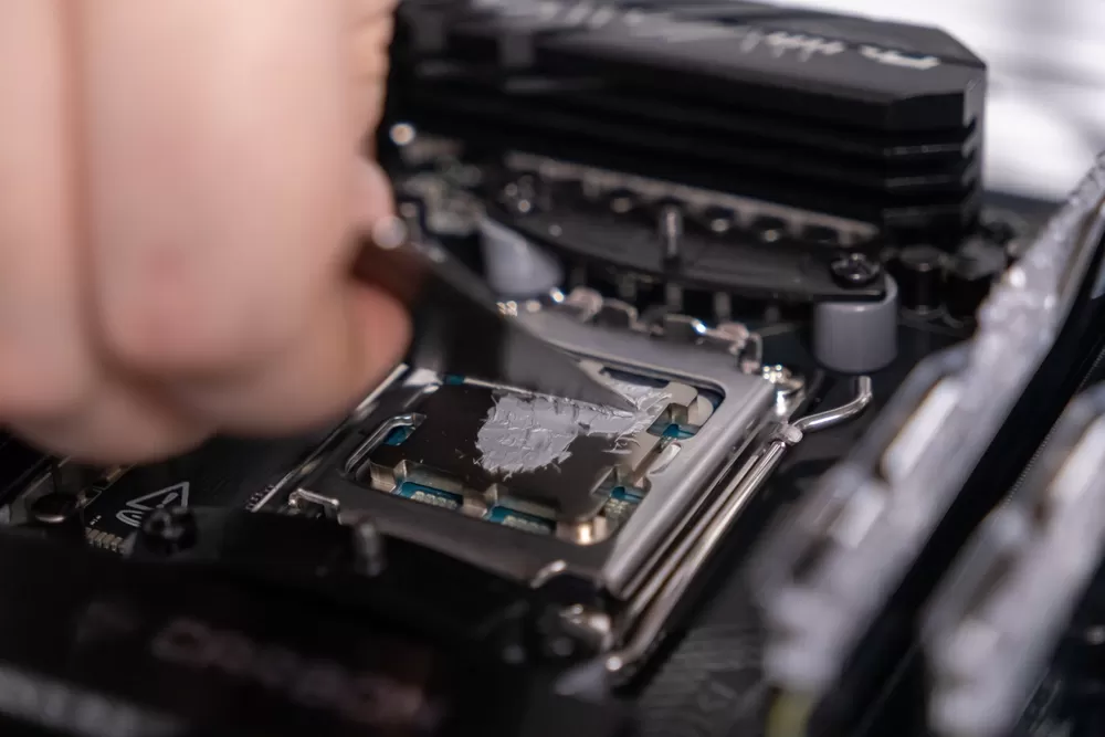
Thermal pads fill air gaps between components and heat sinks for contact. High-performance pads (thermal conductivities of 1-20 W/m·K) assure PCB thermal management. TIMs, including thermal greases, also cut interface resistance by conforming to surface irregularities.
Component Placement Optimization
Position high-heat components near edges or airflow paths to avert hotspots. Separate power amplifiers and digital processors to lower thermal coupling. Distribute components with similar power dissipation to balance the thermal load across the PCB. It avoids localized overheating.
Power Plane Layering
Multiple power planes augment thermal conduction with greater heat-spreading paths. For instance, a 4-layer PCB with dedicated power and ground planes can lower thermal resistance. Isolating power and ground planes improves heat dissipation and keeps electrical isolation.
Thicker PCB Substrates
Thicker PCBs, including metal core substrates like aluminum, are employed in thermal management for high-power designs. Boards thicker than 2 mm may handle larger thermal loads and suit LEDs and motor controllers. Choose thickness per power dissipation and reliability.
Forced Air Cooling
Fans and blowers heighten airflow and diminish surface temperatures. Active cooling is key to high-performance applications, including gaming GPUs. Furthermore, pairing fans with heat sinks raises thermal management efficiency while increasing convective heat transfer.
Liquid Cooling
In extreme cases, liquid cooling uses water or coolant-filled loops to dissipate heat from PCBs. It is necessary for overclocked servers. That's where heat may exceed 100 W/cm². Cold plates with copper tubes give low thermal resistance and heat transfer coefficients above 1000 W/m²K.
Thermal Management Materials
FR4
FR4 is a fiberglass-reinforced epoxy laminate with low thermal conductivity (0.25 W/m·K). It offers stable electrical insulation but fails to dissipate heat in high-power setups. In PCB thermal management, FR4 in uses above 130-140°C Tg risks material degradation and delamination. Heavy copper can improve heat distribution but increases fabrication complexity and costs.
Metal Core PCBs (MCPCBs)
MCPCBs (aluminum or copper core) deliver sufficient thermal conductivity. Aluminum is cost-effective and lightweight for LED lighting. Copper has higher conductivity and benefits MOSFET drivers. In PCB thermal management, the metal layer spreads heat away from critical components. It helps decrease thermal resistance compared to FR4. Nevertheless, CTE mismatch between the metal and dielectric layers demands precise engineering to inhibit stress failures.
Ceramic PCBs
Aluminum nitride (AlN) and beryllium oxide (BeO) are utilized in PCB thermal management. They keep stability up to 1000°C for aerospace and RF uses. E.g., AlN's low CTE (4.3-5.8 ppm/°C) matches silicon die. It lowers thermal stress in high-cycling settings. Ceramics perform well but are fragile, so hybrid designs with metal cladding help balance cost and durability.
Best Practices for Effective PCB Thermal Management
PCB thermal management counts on design and validation strategies. First, thermal simulation tools like ANSYS or FloTHERM can analyze heat dissipation. Focus on hotspots near high-power ICs or dense component clusters. For material selection, prioritize high-Tg laminates like FR408HR (Tg 230°C) for high-frequency applications or polyimide for thermal cycling.
Plus, thermal vias should be embedded near power sources for heat conduction to ground planes. During prototype testing, replicate worst-case scenarios, including maximum ambient temperatures or power surges. Likewise, monitor junction-to-ambient thermal resistance (RθJA) using thermocouples. Refine heat sinks, copper pours, or fans if RθJA is above design limits.
To learn more about the details of solution applications, visit our website.
